
About 20 years ago, actually June of 2002, a fellow named Ron Wodaski published a book “The New CCD Astronomy”, which became the “Bible” for serious astroimagers. It’s still available on Amazon by the way if you have never read it 😊. In that book Ron, who was one of the pioneers of this hobby listed the 3 most important components for success:
1) The telescope mount
2) The telescope mount
3) The telescope mount

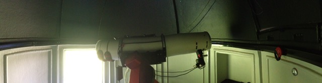
I took this advice to heart and at that time put all my resources into obtaining the one mount that all the top astroimagers were using at the time, The Paramount ME, manufactured by Software Bisque, Golden CO US. On the Paramount I mounted a 30 year old telescope I was gifted when I was a teen. Hardly an “imaging scope” but as Ron predicted I got pretty amazing results with it!

The Paramount was the standard for imaging mounts for years, and still ranks at the top of the list, but of course with time and technology advancements comes the next big thing, and there are several of those now.
Nevertheless, the Paramount ME was perhaps their most consistent performer and certainly was that for me as well, until recently I switched it on and….. nothing happened! The control board finally gave up the ghost, after about 20 years.
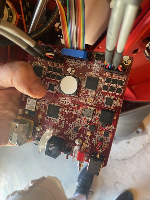
So what to do? The original control board, called the MKS 4000 was of course no longer in production and it was not going to be possible to obtain another one. The next generation boards, the MKS 5000 also not available. What was available was their brand new MKS 6000 board, Upgrading your Paramount with the MKS 6000 telescope control system meant totally new electronics (indeed, their best ever with fewer components), built-in Ethernet and Wi-Fi along with more robust USB Type C communication options, as well as improved through-the-mount power solutions.
Well I certainly could NOT allow this classic mount which gave me years of enjoyment and launched an endless passion for astroimaging, languish as a hulk of dead metal somewhere.
I am not a religious DIYer by any means but I have been one when necessary and this fell into the category of “necessary”. The boards are not cheap and there was quite an additional expense tacked on to that if I was to ship the mount to SB to have it factory installed.
I remember when I first got the Paramount ME, it was so far above anything I had ever seen or used in terms of its’ complexity I was afraid to touch the darn thing.
Well that was all about to change!
The board took nearly 3 months to arrive.
There was a supplemental instructions packet which was basically a parts list and instructions regarding the software part of the installation. There was a link to an “upgrade video” which showed the install on one of the contemporary mounts which was nothing at all like the one I had. Ok so pretty standard for these kinds of things. As I used to say in my surgical career, “you’re all alone in the operating room!”
Thankfully I have a good friend Tom H. (Thank you Tom!) who works with the SB crew and knows these mounts inside and out, so I could consult with him during the process.
Step one was to watch the video. Even though it was not relevant to the classic ME mount I got a sense of the steps, basically remove and install. Step 2 was exposure, kind of like doing surgery. You can’t fix what you can’t see! Then the step by step installation, connect to software and test. It actually went a lot smoother than anticipated! That’s often the case. Always looks worse than it is!
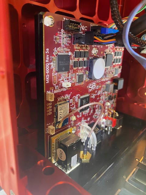
I would say the biggest challenge was figuring out how to secure the new board. The old board was screwed into the right ascension box side panel but the new board had to be placed on the bottom and it was not obvious how to fix it in place, and there were no instructions how to do it! After thinking I had to put some kind of spacer in there and tape everything in place, obviously wrong, but could not see any other way, I discovered there were 2 small holes under the adaptor plate for 2 screws that passed through the board under the plate and fixed it in place. Despite the fact that there was a residual ¼” of space under the board after the fixation, that in fact was the correct configuration as I confirmed with the SB crew!
Here are some images of the installation. For the full length tutorial, see this page
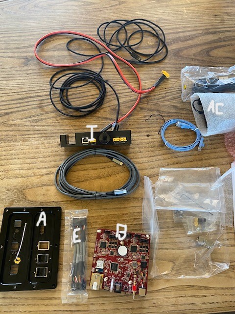
Here is what was in the box. ‘A’ is the new adaptor panel which goes on the rear of the mount. ‘E’ were the 2 motor extension cables which converted the 8 pin motor harnesses to a 10 pin. ‘I’ is the new instrument panel. ‘AC’ is the AC adaptor. The red cable is the new XT60 through the mount power cable. the grey cable below ‘I’ is a 15 foot usb c cable. There is also the light blue ethernet which is also a through the mount cable, a long jacketed black ethernet cable for potential ethernet mount connection, and various screws.
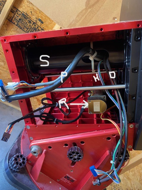
“Exposure” was the key. It was very interesting to find that after removing both panels of the right ascension box and the east dec panel there really was not that much in there! In this image the old control board has been removed. Basically you have the 2 old through the mount cables labeled ‘P’, the Dec and RA (right ascension) motor cables labeled ‘R’ and ‘D’, the homing sensor cable labeled ‘H’ and the RA shaft labeld ‘S’.


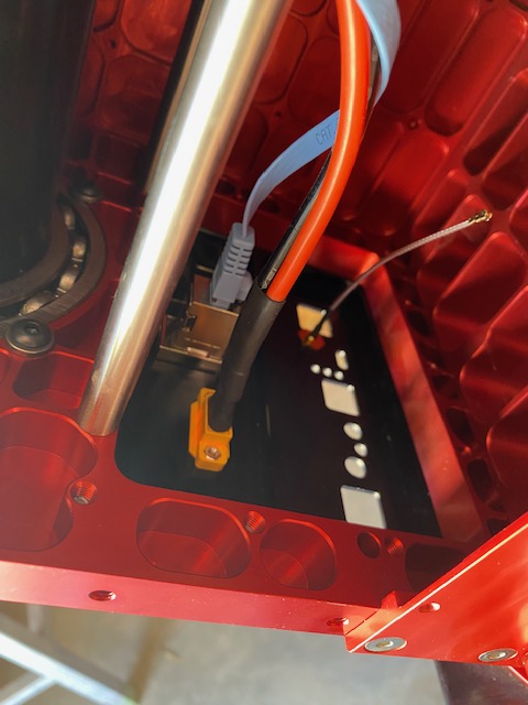
So here like we do in surgery I am “retracting” the motor cables out of the way (white “retractor” drawn in here 🙂 in order to access the back of the adaptor panel. I actually used a zip tie wrapped around the altitude adjustment knob there.


Then after the installation, we turn on the mount, open the Sky X application and execute a process called “homing”. When the mount is homed, it slews to the home position and sets the control system’s “position registers” to zero. Then it knows where it is in space. The home position is approximately 0 degrees declination and hour angle of 2 in right ascension. Those are the two axes on the mount (right ascension and declination) kind of like longitude and lattitude but on the celestial sphere. In this video the mount slews to the home position and you can here 2 audible beeps, one for each axis meaning the homing procedure was successful. There is the first beep and then a second one occurring about 5-8 seconds after. Then the mount will start tracking automatically which it did.
So the upgrade was a success! Yay! Just like anything in life, it may seem overwhelming at first, but as you take small steps toward the goal you realize it wasn’t nearly as bad as you thought. As my wife told me when I was waffling over whether or not to undertake this: “K’mon now, it’s going to be way easier than replacing a shoulder!” She was 100% right.
Thanks for reading!
DrDave


Quite an achievement.
LikeLiked by 1 person
Awesome write up! A couple years back my MX+ started acting up due to a loose USB mini port. I sent it in for a tune up and it’s been sitting in its box until this past week due to my move, etc. When I received it, it was 2 months before they announced the new 6000. I’m bummed as I would have had them upgrade the mount while they had it. I do not have the courage to perform the “surgery” you document. Maybe now after seeing this post I might give it a go!
Funny though- I spent 5 hours in someones brain yesterday and yet I fear opening a telescope mount lol!
Cheers!
LikeLiked by 1 person
Ha! Same exact deal for me. Joint replacements, complex revisions etc etc and always apprehensive with this stuff. Those mini-usb connectors have been a serious flaw. I had to replace 2 5000 boards already. The 6000 looks way more robust though.
Best,
Dave
LikeLiked by 1 person