
Alright possibly like yourself I am not a religious DIYer. I am not an engineer and “I am not a mechanic Jim,..just an old country doctor!” But also like yourself I am the proud owner of a classic Paramount ME and for whatever reason I tried turning it on recently and nothing happened, after 20 years of consistent, uninterrupted usage.
So here we are, if we want to continue using it we must upgrade to the new MKS 6000 system. My old ME had the MKS 4000, so this is an upgrade from that. If you are upgrading from a 3000 it’s going to be basically the same except your old board will look a little different from this one.
This extended blog page will hopefully be of some help to you if you do need help. Please be advised though that this is not an official Software Bisque support page, or document. The content on this page is not endorsed or approved formally by Software Bisque and is just a recounting of my personal experiences with this upgrade, which was completely successful, by the way.
Let’s start with tools you will need:
1) A complete SAE allen wrench set. Not the metric version. It can be helpful to have the ones with the ball tip end to hold the screws in place but not required.
2) Needle nose plier and/or tweezers to retrieve smaller screws that drop into areas of the mount housing
3) Zip ties
4) Sharp pointy Phillips head screw driver that can fit into small screws
Suggested tools include:
1) Voltmeter to confirm the voltage coming out of the AC adaptor
2) A screw extractor set and intermediate size (5mm or so) cobalt drill bit. If you have had your mount for a long time exposed to the elements it is conceivable that one or two screws in one or more of the face plate covers will have become completely bound and will need to be extracted or drilled out. Not a disaster. I had to do this myself. You might be left with one or two screws missing but this is a cosmetic issue and will not affect mount performance. If you have to drill a screw out be careful not to plunge through the casing although most of these screws are on the periphery and there is nothing behind them that can be damaged.
3) A coated tip flat head screw driver to assist separation of the cover panels

Other needed items: The Sky X software. You will need build 13811 or later
General points on this upgrade:
1) I found it actually easier than working on the newer mounts. Once the face covers were removed everything was easily accessible. You will NOT need long zip ties to facilitate passage of cables.
2) You can test the mount with all covers still removed and just the versa plate and counterweight shaft connected.
3) The latest recommendation (as of 5/23/2024) for motor angle measurement is that unlike for the MKS 3,4 or 5000, for the MKS 6000, the timing belts DO NOT have to be removed. Leave the belts on and make sure the mount is placed in balance mode meaning the worms are disengaged..
4) Please note that the worm blocks in the ME DO NOT have to be removed as they do for the more contemporary mounts
5) I used small zip lock bags to put the removed screws in and labeled each bag which part they belonged to.
6) If at any time during the motor angle measurement or getting things otherwise started with The Sky X software you see any message regarding “firmware upgrade” or “firmware error” do NOT go any further. Contact Software Bisque first for further instructions.
Where do I start with this? What do I do?
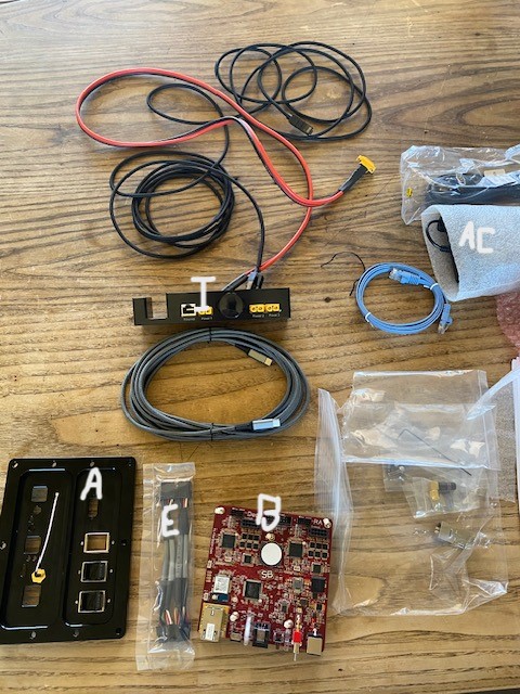
Start by checking the packing list (see image above)
1) Instrument panel
2) *RA and dec motor extension pieces. These allow you to use the existing motor cables and convert the 8 pin terminals on the originals to 10 pin. These can then plug directly into the new board.
3) 2 ethernet cables. There is one jacketed 15 foot long which is for mount connection to ethernet. One 31cm long which is for through the mount
4) 31 cm XT60 through the mount cable
5) MKS 6000 board. Note the board is mounted on a plate and there are two screw holes under the plate on the side that faces the adaptor panel. These holes are for 2 screws that will fix the plate to the panel
6) Adaptor panel. Note there are no electronics on this panel as there are on the back of the old panel
7) Small stuff in small bags: tiny allen wrench with 2 tiny screws for fixing the XT60 through the mount cable to the panel. A pair of small square bags connected to each other, one with 2 screws in it and one with 3. The 3 screws are for the new instrument panel. The 2 screws are to fix the board to the adaptor panel
8) Wifi antenna
9) Ethernet terminal box for adaptor panel

Next thing to do is to find these documents which you will need for reference during the procedure. They can be found on the Software Bisque site under Support > Documentation:
1) Paramount ME User Guide
2) Paramount ME MKS 4000 Electronics Upgrade and Replacement Instructions. This is just to give you some idea of what you will find when you get into the RA box
Next thing to do is to go ahead and watch the upgrade video which is found at https://www.bisque.com/6kvideo
Despite the fact that it describes the procedure for what looks like a Paramount MX+ you can get a general sense of the order in which things are done. What I describe here is going to be way different than that, but a few things are the same.
Basic approach is:
1) Remove instrument panel and versa plate
2) Expose the mount by removing panels
3) Take out the old board, the old cables connecting the board to the adaptor panel, and separate out the 2 motor cables and homing sensor cable
4) Remove the old through the mount cables
5) Install the new adaptor panel and new through the mount cables
6) Replace the versa plate and install new instrument panel
7) Install the new control board
8) Turn on the mount, load TSX and do the motor angle measurements
9) Put the mount back in tracking mode, do a homing test, exercise mount.
Now let’s get started for real:
1) Remove your scope if it’s still on there
2) Remove the counterweights and I would say for now remove the counterweight shaft
3) Take off the worm block covers as you would for relubricating the mount. Even though you can leave the worm blocks as is, you are probably going to want to clean things up, relube etc. You’re going to expose basically the whole mount so probably a good idea to look at these as well.
4) Remove the small screws in the front of the instrument panel and when this is separated remove the 2 cable terminal plugs from the panel.


5) Remove the Versa plate on top. There are 8 cap screws in a circle and 4 central screws in a square.

6) Remove the back part of the instrument panel that screws into the underside of the Versa plate. The old instrument panel was in 2 parts. The new one has just one piece that requires 3 screws. None of these removed parts or screws will be needed for the new panel
7) There is a thin plate with 6 screws that covers the channel in the Versa plate for the cables. This sits immediately behind the instrument panel.(see image) Remove this piece and the screws but save it because you will reinstall that with the new panel

The top of the dec housing should now look like this with the 2 cables exiting:

8) The next thing to do is to remove the covers on both sides of the RA box, east and west. The screws to remove are identical. There are several cap screws around the periphery (see image). You will have to raise the altitude of the mount to access the small Phillips head screws at the bottom of the panel (see image). Make sure you have a sharp pointy Phillips head driver that fully engages these screws because they can be stripped.

a. The EAST panel is what the old control board is screwed onto. Be careful when separating this panel that you don’t put too much traction on the attached cables because 3 of them need to be preserved. I found there to be plenty of slack when I took it off so don’t be concerned about it, just be aware.


9) Once the east panel is separated carefully remove the RA and dec terminals. Those are the ones associated with the black cables, one group on either side of the board. Refer to document #2 above and also to the images. Also remove the homing sensor cable which is the rainbow colored one that you can see travels with the motor cables with a part of it going up into the RA shaft with the dec motor cables and part going with the RA motor cables. The RA motor is right there inside the RA box, so it’s very clear which motor cables are RA as they go right to that motor. The dec motor cables go up into the RA shaft toward the dec motor. If you need to be sure, put a zip tie around one group and make a note that “this is the dec” or “this is the RA” so you don’t mix them up.

10) Remove the 2 power cables that go from the control board to the adaptor panel. See accompanying images. These cables you will not need. There is no control board on the new adaptor panel. Remove the control board from the east RA panel. Those are tiny cap screws that hold the board on. You will not need any of this stuff for the new install
11) Remove the old adaptor panel. Keep those screws because the same ones are used for the new panel.


.
Review video 1. The following short video is just reviewing the previous steps:
12) Remove the west side RA panel. Note the 2 through the mount cables going from the adaptor panel up into the RA shaft. This is a different arrangement from what you see on the newer mounts. The through the mount cables actually go INTO the RA shaft, not around it. (see above image)
13) Remove the east side dec panel (see image below). After removing the cap screws around the edges you will need to turn that tiny screw in the lower left corner and when you do that the panel will separate. Note that there really isn’t much in the dec space. The 2 through the mount cables come up from the RA shaft into the space and then go into a similar hole in the dec shaft up to the top.


14) Remove the old through the mount cables. You can see they are zip tied to the RA shaft. Note the location with a zip tie around the center of that hole and the length of cabling from that point to the adaptor panel. You can cut the ties off. We will reproduce that arrangement with the new cabling. Pull the cables down through the dec shaft at the top and then down the RA shaft. Everything as you can see is very accessible. You can follow the cables down very easily, pushing the terminals along the way. You will not need to use a zip tie to guide the cabling out.
15) Remove that curious looking strap that’s right in the middle of everything. (see image). This was a “heat sink protector” that kept the cables from contacting a heat sink on the old board. You won’t need that for the new control board.

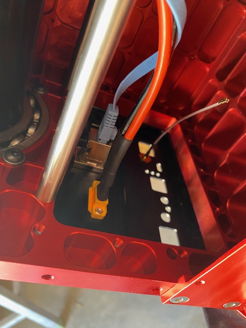
16) Install the new adaptor panel (see images). Use the same screws from the old panel to secure the new one on the back of the RA box. Clip on the metal ethernet terminal box onto the port in the back of the panel. There is a slot on the terminal frame both top and bottom. The vertical orientation is not critical. Either up or down, whichever way is more stable. I think I put the clip down. The wifi antenna we will secure to the board once that is installed.


17) Next we will install the new through the mount cables. Put a zip tie around the 2 cables (XT60 and ethernet). Note the blue ethernet cable is the one used for through the mount. The long 15 foot cable is the one for external mount connection. The location of the zip tie will be approximately the same as the in the old set up (see image). Plug the cables into the adaptor panel. Now run the cabling up through the RA shaft into the dec space. Put a zip tie through the one placed around the cables at the RA shaft hole and secure the tie circumferentially around the shaft. This separates the through the mount cabling from the motor cables as shown.


18) In the dec space we will loop the through the mount cabling around the back of the dec shaft to avoid interaction with the dec motor cabling and binding on the dec shaft itself. This is the recommended configuration for through the mount cabling as specified in the Paramount ME manual.

19) Finally pass the 2 cables out through the top of the dec housing as shown.

Review video 2. The following is a short video recapping the steps above. Please disregard the sections related to exposure of the motors, timing belts etc as these steps are no longer required
21) Next plug the through the mount cables into the new instrument panel (see image). The new instrument panel is just one piece.

22) On the underside of the Versa plate you’ll see one side has the channel for the cables. This is the side the instrument panel goes on. There are only 3 screws needed to fix the panel to the plate (see packing list section) and you will see how the panel aligns flush with the edge of the Versa plate. The cables should then run through the channel into the instrument panel as shown.

23) Next screw on that thin plate you removed before using the 6 small screws.. (see image). That plate sits right behind the instrument panel and just holds the cables in the channel.
24) Position the Versa plate back onto the dec housing and take any slack out of the cables by pulling on the section in the dec box where there is a lot of room there for extra cable length. Make sure the cables aren’t pinched when you screw the Versa plate back on.
25) ** Before fixing the versa plate back onto the dec housing note the arrow that’s etched in there and the direction it’s pointing. The arrow points in the direction of INCOMING light. I screwed this up the first time. Easiest way to think about it is that it points TOWARD the instrument panel, so that should be the orientation of the plate (see image)

26) The plate is fixed initially with the 4 cap screws in the center, followed by the 8 peripheral socket screws (see image of the removal step above)). I just centered the plate as it was before. The exact position can be changed if needed. Main thing is to make sure the orientation is correct.
27) Next find the 2 motor extension cables for the RA and dec (see packing list image). These cables convert the old 8 pin terminals to 10 pin terminals. *They are interchangeable. There is no grey dot as described in the supplemental instructions, at least in my package. This is no problem. All that matters is you connect the ends properly and the RA cable and dec cable go into their proper positions in the board. Remember the 8 pin side connects to the original 8 pin terminals and the 10 pin side will connect to the board.
28) Starting with the old 8 pin terminal ends, connect those terminals into the 8 pin ends of the extension pieces (see image). They connect “tab to tab” as shown.

29) Now we connect the 3 cables to the new board. Start with the homing sensor cable. The brown wire at the edge of the “rainbow” points to the dec side. You will see that is the only way it can go in because the arrow in the center of the terminal has to go in the slot facing the center of the board. Connect the dec and RA motor cables. See page 11 figure 12 in the supplemental instructions. The 10 pin terminal tabs are oriented toward the top. It’s basically tab to tab.

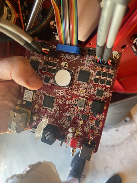
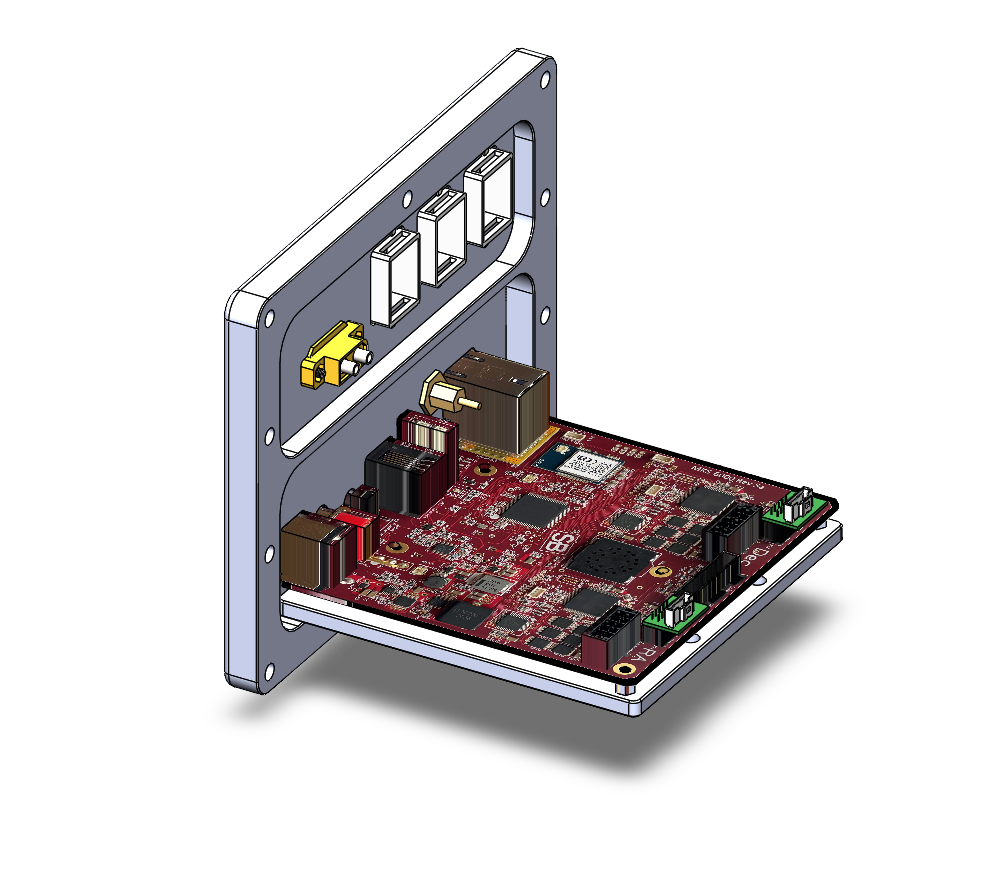
30) Once the 3 cables are inserted into the board you can carefully insert the board onto the bottom of the RA box and place it against the adaptor panel so that the outgoing ports and switches etc are properly engaged into the adaptor panel (see images). Once it is in the right spot it should stay fairly securely until you place the locking bolts. You will notice there is about a ¼” space below the board once positioned. This is the correct alignment!
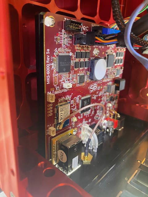
31) Take the 2 screws from the small packet (see packing list images). Screw these into the 2 holes on the bottom edge of the adaptor plate (see image), one on each side. Those screws should fully seat so that they are flush with the edge of the adaptor plate. Once these are tight, the control board should not be moveable at all. The final alignment/ configuration should look like the illustration below.

32) Next insert the internal wifi antenna. This presses onto the board as shown (see image above). You have to tilt the antenna up a little to get it seated properly.
33) Screw on the external wifi antenna onto the adaptor panel where is says “antenna”
Review video 3. This is a short video reviewing the previous steps. Please disregard any sections related to disengaging motor pulleys as these steps are no longer required
35) We are now ready to power up the mount! Before that I think it’s a good idea to check the voltage coming out of the AC adaptor and make sure it’s around 48 volts, not lower (see image). Not all outlets are the same. I tend to meter everything in this business as it will rule out potential unanticipated problems.

36) Now go to page 25 of the supplemental instructions book and follow those directions right through to page 27. Again, you DO NOT need to remove motor pulley belts. Just disengage the RA and dec worms and leave the belts on (balance position).
37) When you turn the mount on you’re going to hear continuous beeping from the mount until the motor angle measurement is done and the motors are initialized.
38) ** After you choose the correct mount in TSX telescope setup (Paramount ME), you still need to click on settings and choose the correct COM port just like you may have done when there was an MKS driver to deal with. Thankfully there is no driver anymore! You should see MKS6000 in the drop down right away (see images)


39) Once you have completed the motor angle measurement process as described in the manual and the mount is rebooted, there should be no more continuous beeping. If there is, check the section in the manual on “MKS troubleshooting”
Angle measurements are typically around HA 750, Dec 430 or so. All motors are different. If the mount powers up normally, no beeping then most likely everything is good.
**If at any time you see any messages that pop up concerning either firmware error or upgrading firmware DO NOT proceed further and contact Software Bisque for further instructions
40) Next test is to shut down everything and restart. When you turn the power on there is that initial power up sound followed by the usual short beeps which it sounds like there are 3 of those now. All the lights should be on. In TSX when you connect to the mount you should get the usual prompt “mount has not been homed. Would you like to home the mount?” This time click on “yes”. You should see something like in this homing video below. When the mount successfully homes there should be 2 beeps, in this case several seconds apart. After homing is successful the mount should start tracking automatically.
41) Finally you should exercise the mount. In TSX go to the mount tools > Bisque TCS (as before) > utilities > exercise mount. There is the default 6 cycles which should be fine. Then you can relube the worm gears as needed. Here is what the exercise test looks like. I think I recorded about 4 of the 6 cycles.
Very important to take advantage of the “open mount” during the exercise test to watch it and make sure there are no cable snags or other complications related to cabling inside the RA or dec spaces during this process.
42) I redid the homing test once everything was put back together. All good!
Notes on the handpad
A handpad does not come with this package. You cannot use your old MKS 3 or 4000 joystick with this. You can use an MKS 5000 handpad with it but it is recommended to calibrate the handpad first. See page 28 of the supplemental instructions for step by step on how to do that.
Congratulations! You now have upgraded your Paramount ME with the latest and greatest control system 😊!


